Field guide
From design triangles to a defensible point report
Confirm the design and reference before calculating, then explain both results and exceptions.
Compare a position with a design, without matching point names
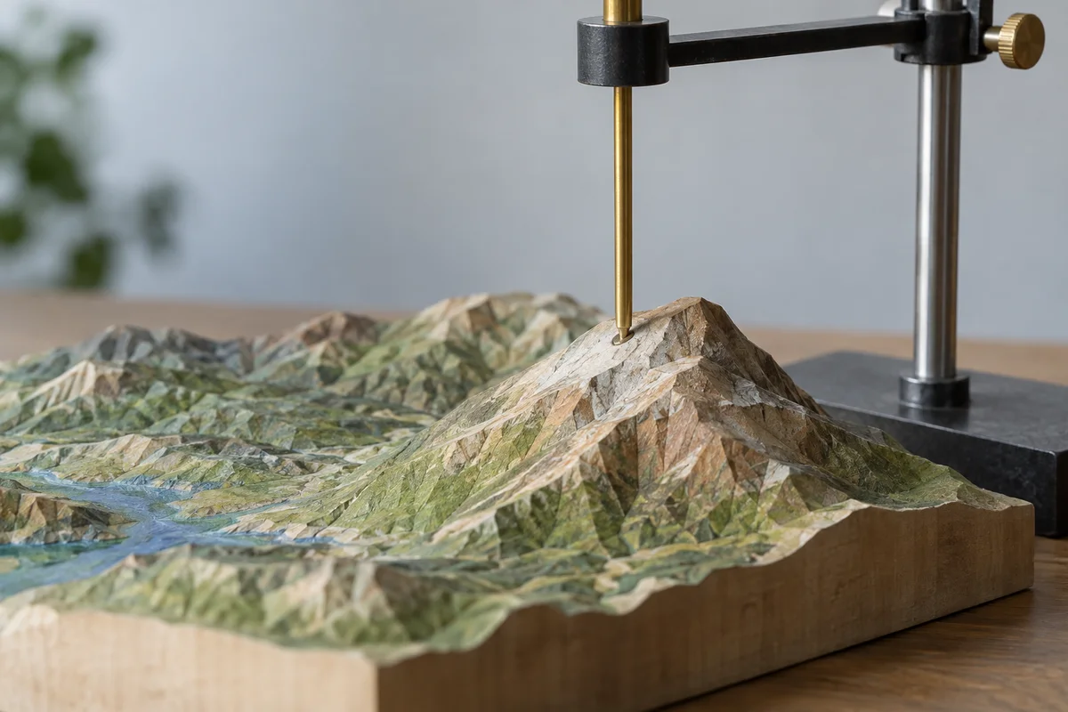
Point to surface comparison answers a different question from matching a design point list to a measured point list. You have an observed position, but there may be no design point with the same identifier or exactly the same coordinates. A TIN supplies a piecewise planar surface, so the tool can find the original triangle covering that position and interpolate a design elevation there.
Use the query-only mode when you need a design height at an Easting and Northing. Use comparison mode when a measured elevation is also available. The latter returns measured minus design, together with the source record, contributing face records and a status. It does not require the measured point name to match any vertex name in the design file.
Choose the correct surface and revision first
Load a LandXML 1.1 or 1.2 file and explicitly select its design surface. A single document can contain existing ground, finished grade, subgrade and other surfaces with similar names. Read the selected name, units and structural issues before supplying points. The file name alone is not a reliable instruction about which surface to use.
The calculation uses an explicit TIN Definition and its original active triangles. It does not create a surface from scattered points, rebuild breaklines, interpolate a raster or combine several surfaces automatically. If the file contains only source points or unsupported geometry, ask the author for a current triangle export. The original file and selected object remain part of the calculation report.
Confirm reference and units across both files
Both inputs must describe the same planar horizontal reference and the same vertical datum. Selecting metres from a list does not transform a national-grid coordinate, move a local origin or convert an ellipsoidal height to an orthometric elevation. A plausible result at one location cannot establish that two datasets use compatible references.
The current workflow requires the point horizontal and height units to match the surface linear unit: metre, international foot or US survey foot. There is no implicit conversion. A known unit received from another tool is checked against your choice. Record the reference, height meaning, design revision and purpose in the note, then confirm both the field mapping and the surface relationship.
Prepare the query or observation table
Upload CSV, TXT or XLSX, or paste a small table. For a workbook, choose the intended worksheet before mapping columns. The tool keeps source row identities and original fields, so repeated names remain separate observations. Map Easting and Northing explicitly; the optional point name and description help you locate records but do not control the interpolation.
Comparison mode requires a numeric measured elevation on every record being compared. Query-only mode can omit that field by assigning column zero. Missing values, malformed rows or invalid numbers remain visible as invalid input; they are not changed to zeros or silently removed. Formula cells in a workbook must be replaced with reviewed values before import.
How the design elevation is calculated
For a location inside a triangle, the tool calculates barycentric weights in the Easting/Northing plane. Applying those weights to the three vertex elevations gives the height of that triangle plane at the requested position. The calculation uses coordinates relative to one vertex, which reduces unnecessary dependence on a large project origin.
It uses the supplied triangle connectivity rather than a newly generated Delaunay mesh. The JSON records the candidate face identities, vertex identities, interpolation weights and candidate heights for each solved location. Those details let you independently reproduce a result from the original file. A number displayed to many decimal places is still an interpolation from the supplied design, not evidence of equivalent field accuracy.
Interpret positive and negative height differences
The sign convention is fixed: delta Z equals measured elevation minus design elevation. A positive value means the observation is above the selected design plane. A negative value means it is below. Read that literal relationship before assigning an earthwork action: whether material should be removed or added depends on the purpose and stage of your project.
The optional tolerance is an absolute height difference in the selected height unit. Values inside or on that threshold are marked within tolerance; larger positive and negative differences are marked above and below. The tool supplies no universal construction acceptance limit. Choose a documented project threshold, and do not confuse a tolerance status with a measurement uncertainty assessment or certification.
Do not invent heights beyond supported coverage
If no active triangle contains a point, the design elevation remains blank. The status identifies that it is outside the mesh or in an area without triangles. The tool does not extrapolate the nearest face, substitute the closest vertex or stretch the convex hull across an opening. This applies even when an outside point is close to a visible surface edge.
Invisible faces remain excluded. Supported explicit outer boundaries restrict coverage, and hide rings exclude their interior, including the ring boundary conservatively. Invalid or unsupported boundary definitions block the selected surface instead of being silently ignored. A geometric extent is only a bounding box; it is not a promise of complete coverage inside that rectangle.
Handle shared edges and overlapping triangles separately
A valid query may lie on an edge or vertex shared by neighboring triangles. When the candidate heights agree within the implementation numerical comparison tolerance and all candidates are boundary hits, the result is accepted and the contributing face records are retained. The numerical comparison threshold is separate from your engineering acceptance tolerance.
If candidate triangles overlap at the query location, or their boundary heights conflict, the result is marked ambiguous and no design height is chosen. The tool does not pick whichever triangle happened to occur first in the XML. Structural checks also reject degenerate faces, missing references and non-manifold edges. This is a location-based check, not a certificate that every unsampled region of a large mesh is free of overlaps.
Read the map and the complete result table together
The plan view places the original mesh under query-point markers. In comparison mode, red indicates above design, blue below and green within the chosen tolerance. Amber marks a location without a resolved comparison. Click a displayed point or use arrow keys to move to its table page, then read its numeric values and explanation.
The drawing is limited to 15,000 triangles and 1,500 markers, while calculations and downloads use all accepted input records within the documented file limits. An outlying coordinate can expand the plot extent and make the design look small. Investigate that record rather than assuming the surface has disappeared. The drawing does not provide a basemap or automatically establish the project location.
Export evidence that preserves exceptions
The comparison CSV and XLSX include every row, including invalid, outside and ambiguous records. Unresolved calculated values remain empty, with a status or error beside them. A blank does not mean zero difference or a passing observation. Review the summary counts before using a spreadsheet filter that might hide unresolved records from a supervisor.
The JSON contains both inputs, selected design, reference note, mode, units, tolerance and interpolation details. Save it with the source revision when results need to be reproduced. This report describes vertical differences at discrete locations. It does not integrate earthwork volume, calculate a perpendicular distance to a slope, account for pavement thickness automatically or certify construction quality.